TM 9-2350-261-20-l
CHARGING SYSTEM MALFUNCTIONS
INITIAL SETUP
Tools:
General Mechanic’s Tool Kit (Item 30, App D)
Inspection Mirror (Item 42, App D)
Digital Multimeter (Item 43, App D)
Jumper Wire
STE/ICE-R Test Set (Item 71.1, App D)
Personnel Required:
Unit Mechanic
References:
See your -10
STE/ICE-R charging circuit troubleshooting
(page 3-256)
Equipment Conditions:
Engine stopped/shutdown (see your -10)
Carrier blocked (see your -10)
Trim vane lowered (see your -10)
Power plant front access door open
(see your -10)
Driver’s power plant access panel removed
(see your -10)
Power plant rear access panels removed
(see your -10)
Engine disconnect lever IN (see your -10)
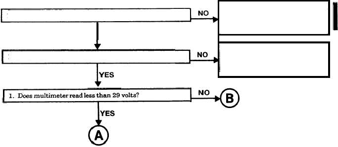
1. Start engine and run at 1200 RPM (see your -10).
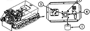
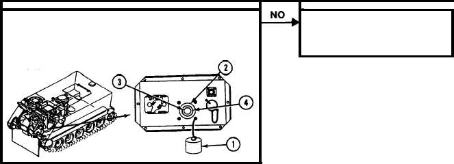
2. Remove cap (1) from slave receptacle (2).
3. Measure voltage between contacts (+) (3) and (-) (4) on
auxiliary power receptacle.
4. Does multimeter read less than 26 or more than 29
volts?
1. Stop engine (see your -10).
2. Go to battery/generator
indicator malfunctions
(page 3-143).
1. Belt needs adjustment
1. Is generator belt tight or in good condition?
or replacement
100 amp (page 9-31).
YES
200 amp (page 9-34).
1. Has regulator been adjusted?
1. Adjust regulator when all
other troubleshootingis com-
plete. (page 9-38).
2. Verify no faults found.
GO TO PAGE 3 - 61
GO TO NEXT PAGE
Change 4
3-55