TM 9-2350-247-34
REPAIR FAN ASSEMBLY (M548A1) — Continued
0014 00
6.
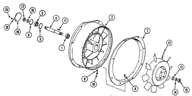
Install bellring (7), 10 screws (8), washers (9) and new lock nuts (10) on fan housing.
7.
Insert rotor shaft key (11) in rotor shaft (4) and install fan (12) on rotor shaft. Gently tap fan in place to clear threaded
end of rotor shaft.
8.
Install washer (13), new lock washer (14) and nut (15) on rotor shaft (4). Torque nut to 150-170 lb-ft (204-232 N•m).
9.
Install new lock washer (16) and nut (17) on rotor shaft (4). Torque nut to 150-170 lb-ft (204-232 N•m).
10. Apply a light coat of antiseize compound to clean threads of four screws (18).
11. Install cover plate (19), four new lock washers (20) and screws (18) to fan housing.
FOLLOW-THROUGH STEPS
1.
Install fan assembly on carrier (see your -20).
END OF TASK
0014 00-4