TM 9-2350-247-34
REPAIR FAN ASSEMBLY (M548A1)
0014 00
THIS WORK PACKAGE COVERS:
Disassembly (page 0014 00-1).
Assembly (page 0014 00-3).
INITIAL SETUP:
Maintenance Level
Direct Support
Tools and Special Tools
General Mechanic’s Tool Kit (WP 0078 00, Item 68)
Retaining Ring Pliers (WP 0078 00, Item 39)
Universal Puller Kit (WP 0078 00, Item 43)
Torque Wrench (WP 0078 00, Item 85)
Materials/Parts
Antiseize compound (WP 0080 00, Item 6)
Lock nut (10)
Lock washer (2)
Lock washer (4)
Personnel Required
Track Vehicle Repairer 63H
References
See your -20
Equipment Condition
Fan assembly removed from carrier (see your -20)
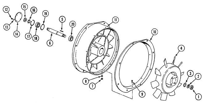
DISASSEMBLY
1.
Remove rotor retaining nut (1), lock washer (2), washer (3), fan (4), and rotor shaft key (5) from rotor shaft (6). Use
puller to remove fan from shaft. Discard lock washer.
2.
Remove 10 lock nuts (7), washers (8), screws (9), and bellring (10) from fan housing (11). Discard lock nuts.
3.
Remove four screws (12), lock washers (13), and cover plate (14) from fan housing (11). Discard lock washers.
0014 00-1