TM 9-2350-287-20-1
8-2. SHIFT CONTROL LINKAGE REPAIR (continued).
3.
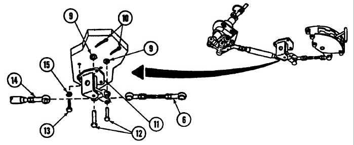
Remove two cotter pins (10), washers (9), and pins (12) from bellcrank support (11 ) and two assembled rods (6
and 14). Remove assembled rod (6) and discard cotter pins.
4.
Remove three screws (13) and lockwashers (15) and bellcrank support (11) from bulkhead (3). Discard
lockwashers.
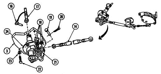
NOTE
Quick-release pin is located in powerpack compartment at driver's bulkhead.
5.
Remove quick-release pin (16) from control assembly (24) and assembled rod (17).
6.
Disconnect four electrical leads (18) from neutral safety switch (21).
7.
Remove four screws (22) and lockwashers (23) and control assembly (24) from bulkhead (3). Discard
lockwashers.
8.
Remove cotter pin (20), pin (19), and assembled rod (14) from control assembly (24). Discard cotter pin.
Change 1 8-3