TM 9-2350-287-20-1
8-2. SHIFT CONTROL LINKAGE REPAIR
This Task Covers:
a.
Removal
b.
Disassembly
c.
Cleaning and Inspection
d.
Assembly
e.
Installation
f.
Adjustment
Initial Setup:
Tools/Test Equipment:
Spring pin (Item 356, Appendix H)
General mechanic's tool kit (Item 24,
Spring pin (3) (Item 360.1, Appendix H)
Appendix I)
Spring pin (Item 364, Appendix H)
Measuring tape (Item 35, Appendix I)
Spring pin (Item 366, Appendix H)
Wire (Item 381, Appendix H)
Materials/Parts:
Drycleaning solvent (Item 27, Appendix D)
Equipment Conditions:
Lubricant, solid film (Item 38, Appendix D)
Vehicle parked on level ground (refer
Lubricant, solid film (Item 38.1, Appendix D)
to TM 9-2350-287-10).
Rag (Item 56, Appendix D)
Transmission access doors opened (refer
Cotter pin (5) (Item 14, Appendix H)
to TM 9-2350-287-10).
Lockwasher (15) (Item 175, Appendix H)
Driver's hatch cover opened and secured
Lockwasher (3) (Item 177, Appendix H)
(refer to TM 9-2350-287-10).
a.
REMOVAL
1.
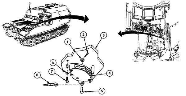
Remove cotter pin (2), washer (1), pin (5), and assembled rod (6) from shift quadrant (4). Discard cotter pin.
2.
Remove three screws (7) and lockwashers (8) and shift quadrant (4) from driver's bulkhead (3). Discard
lockwashers.
Change 1 8-2