TM 9-2350-287-20-1
7-19.
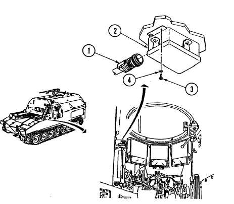
STE/lCE RESISTOR BOX REPLACEMENT.
This Task Covers:
a. Removal
b. Installation
Initial Setup:
TooIs/Test Equipment:
l General mechanic’s tool kit (Item 24,
Appendix I)
Materials/Parts:
l Lockwasher (4) (Item 196, Appendix H)
Equipment Conditions:
l Vehicle parked on level ground (refer to
TM 9-2350-287-10).
l MASTER switch set to OFF (refer to
TM 9-2350-287-10).
l Driver’s hatch cover opened and secured (refer
to TM 9-2350-287-10).
l Battery ground cables disconnected (para 7-41).
a.
REMOVAL
1.
Disconnect STE/lCE control
cable (1) from STE/lCE resistor
box (2).
2.
Remove four screws (3) and
Iockwashers (4) and STE/lCE
resistor box (2) from driver’s
compartment
bulkhead.
Discard Iockwashers.
b.
1.
2.
INSTALLATION
Install STE/lCE resistor box (2)
on driver’s compartment
bulkhead with four screws (3)
and new Iockwashers (4).
Connect STE/lCE controllable
(1) to STE/lCE resistor box (2)
FOLLOW-ON MAINTENANCE:
l Connect battery ground cables
(para 7-41).
l Close driver’s hatch cover (refer to
TM 9-2350-287-10).
7-59