TM 92350-287-20-1
I
2-19. TROUBLESHOOTING CHART (continued).
Iw. CREW AFES (continued).
(3) FIRE EXT. LED’S ARE LIT. FAULT LAMP REMAINS
ON.
Initial Setup:
Tools/Test Equipment:
Equipment Conditions:
• Digital multimeter (DMM) (Item 13, Appendix 1)
• Left and right projectile rack assemblies moved
• General mechanic’s tool kit (Item 24,
to rear of vehicle (refer to TM 9-2350-287-10).
Appendix 1)
(for crew extinguishers 1 and 2 only).
• Crew AFES test./alarm panel MAINT switch in
Materials/Parts:
maintenance position (para 21-3).
l Cleaning compound (Item 19, Appendix D)
• Sealing compound (Item 58, Appendix D)
NOTE
l Instead of using
multimete
for voltage
check, STE/lCE
troubleshooting,
INDIVIDUAL
BATTERY VOLTAGE TEST-TEST
89 maybe performed.
• Instead of using multi meter
for continuity check, STE/lCE
troubleshooting, TEST 91 may
be performed.
A. 1. Inspect all six electrical connectors for mois-
ture, contamination, or loose fit.
I
IAre all connections clean, dry, and secure?
I
I
Clean connectors with cleaning compound
and apply sealing compound to connectors
and reinstall. Very promblen is solved.
m
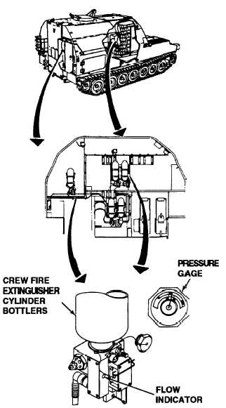
B. 1. Check for protruding flow indicator of
valve actuators of crew fire extinguisher
cylinder bottles 1 thru 6 as indicated by
LEDs on crew T/A paneI.
2. Check pressure gage of crew fire extin-
guishers. Black needle of pressure gage
should be inside green temperature
wedge.
Is pressure gage needle in the correct position,
and flow indicators are not protruding from their
valves?
Continued on next page
2-353