TM 9-2350-287-20-1
12-19. TROUBLESHOOTING CHART (continued).
m. BILGE PUMP (continued).
(1) BILGE PUMP DOES NOT OPERATE. All other
electrical systems operate.
Initial Setup:
Tools/Test Equipment:
Equipment Conditions:
Digital multimeter (DMM) (Item 13, Appendix 1)
Transmission access doors open (refer to
General mechanic’s tool kit (Item 24,
TM 9-2350-287-10).
Appendix 1)
Engine intake grille open (refer to
TM 9-2350-287-10).
Materials/Parts:
Wire (Item 77, Appendix D)
Personnel Required: Two
NOTE
l Instead of using multi meter
for voltage check, STE/lCE
troubleshooting,
INDIVIDUAL
BATTERY VOLTAGE TEST-TEST
89 maybe performed.
Instead of using multi meter
for continuity check, STE/lCE
troubleshooting, TEST 91 may
be performed.
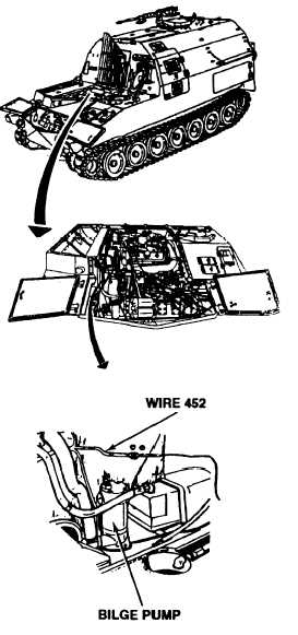
A. 1. Disconnect wire 452 from bilge pump.
2. Place red lead of multimeter in wire 452
and black lead to ground.
3. Have assistant turn MASTER switch ON
(refer to TM 9-2350-287-10).
4. Turn BILGE PUMP switch ON.
5. Check for 24 + 3 vdc.
6. Turn BILGE PUMP and MASTER switch
OFF (refer to TM 9-2350-287-10).
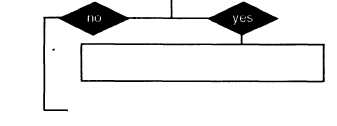
Is voltage indicated?
Replace bilge pump (para 16-3). Verify
problem is solved.
Continued on next page
2-230