TM 9-2350-287-20-1
2-19. TROUBLESHOOTING CHART (continued).
m. BILGE PUMP (continued).
(1) BILGE PUMP DOES NOT OPERATE. All other
electrical systems operate (continued).
CONTINUED FROM C
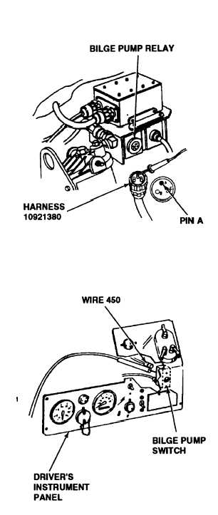
D. 1. Place red lead of multimeter in pin A wire
450 and ground black lead.
2. Turn MASTER switch and BILGE PUMP
switch ON (refer to TM 9-2350-287-10).
3. Check for 24 + 3 vdc.
4. Turn MASTER switch and BILGE PUMP
switch OFF (refer to TM 9-2350-287-10).
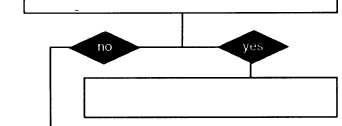
Is voltage indicated?
Replace bilge pump relay (para 7-3).
Verify problem is solved.
E. 1. Reconnect wire harness 10921380 to
bilge pump relay.
2. Remove six screws from driver’s instru-
ment panel control plate. Remove control
plate for access to bilge pump switch.
3. Disconnect wire 450 of harness 12260287
at BILGE PUMP switch output.
4. Place red lead of multimeter in BILGE
PUMP switch output and ground black lead.
5. Turn MASTER switch and BILGE PUMP
switch ON (refer to TM 9-2350-287-10).
6. Check for 24 + 3 vdc.
7. Turn MASTER switch and BILGE PUMP
switch OFF (refer to TM 9-2350-287-10).
Is voltage indicated?
Continued on next page
2-232