TM 9-2350-277-20-5
ADJUST FLAME DETECTOR SWITCH
0727 00
THIS WORK PACKAGE COVERS:
Adjustment (page 0727 00-1).
INITIAL SETUP:
Maintenance Level
Unit
Tools and Special Tools
General Mechanic’s Tool Kit (WP 0926 00, Item 65)
Materials/Parts
Sealing compound (WP 0928 00, Item 56)
Personnel Required
Unit Mechanic
Equipment Condition
Flame detector switch removed (WP 0734 00)
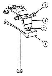
ADJUSTMENT
1.
Loosen mounting screws (1).
2.
Back off adjusting screw (2) until switch (3) clicks.
3.
Turn screw (2) slowly in until switch (3) just clicks. Then turn screw exactly 3/4 turn past the click point.
4.
Tighten mounting screws (1).
5.
Cement screw (2) to mount (4) with sealing compound.
FOLLOW-THROUGH STEPS
1.
Install flame detector switch (WP 0734 00).
END OF TASK
0727 00-1/2 blank