TM 9-2350-277-20-4
REPLACE TORSION BAR — Continued
0413 00
6.
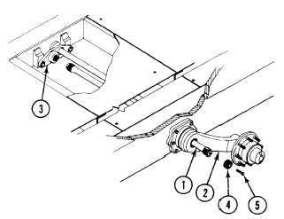
Install screw (5) in plug (4).
NOTE
You may need to jack carrier to raise road arm, before positioning road wheel lifter.
7.
Position road wheel lifter (WP 0426 00).
FOLLOW-THROUGH STEPS
1.
Install floor plates for third and fourth torsion bars (WP 0539 00), (WP 0540 00), (WP 0541 00), (WP 0542 00),
(WP 0543 00), (WP 0544 00), or (WP 0545 00).
2.
Install driver’s rear floor plate for second torsion bar, left side only (WP 0453 00).
3.
Install power plant rear access panel for second torsion bar, right side only (see your -10).
4.
Install driver’s front floor plate for first torsion bar, left side only (WP 0453 00).
5.
Install power plant for first torsion bar, right side only (WP 0156 00).
6.
If removed, install shock absorber (WP 0435 00).
7.
Install road wheel (WP 0426 00).
8.
Install track shroud and covers (WP 0438 00).
9.
Unblock carrier (see your -10).
10. Road test carrier to check that torsion bar is installed right (WP 0155 00).
END OF TASK
0413 00-5/6 blank