TM 9-2350-277-20-3
REPLACE HORN SWITCH — Continued
0293 00
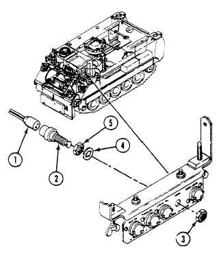
INSTALLATION
1.
Install nut (5) and lockwasher (4) on HORN switch (2).
2.
Install HORN switch through rear of warning light panel. Secure with nut (3).
3.
Connect circuit 25/25A connector (1) to rear of HORN switch (2).
FOLLOW-THROUGH STEPS
1.
Connect battery ground strap (WP 0337 00), (WP 0338 00), or (WP 0339 00).
2.
Turn MASTER SWITCH to ON (see your -10).
3.
Press HORN switch to check for proper operation (see your -10).
4.
Turn MASTER SWITCH to OFF (see your -10).
END OF TASK
0293 00-2