TM 9-2350-277-20-3
REPLACE HORN SWITCH
0293 00
THIS WORK PACKAGE COVERS:
Removal (page 0293 00-1).
Installation (page 0293 00-2).
INITIAL SETUP:
Maintenance Level
Unit
Tools and Special Tools
General Mechanic’s Tool Kit (WP 0926 00, Item 65)
Personnel Required
Unit Mechanic
References
See your -10
Equipment Condition
Engine stopped (see your -10)
Carrier blocked (see your -10)
Battery ground strap disconnected (WP 0337 00),
(WP 0338 00), or (WP 0339 00)
REMOVAL
NOTE
Two nuts and lockwashers come with new switch.
1.
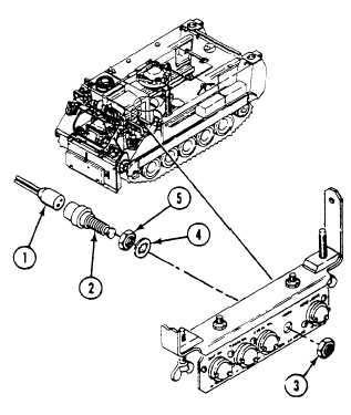
Disconnect circuit 25/25A connector (1) from rear of HORN switch (2).
2.
Remove nut (3) and HORN switch (2) from warning light panel.
3.
Remove lockwasher (4) and nut (5) from HORN switch (2).
0293 00-1