TM 9-2350-277-20-2
REPLACE FUEL CONTROL SHAFT AND LINKAGE — Continued
0217 00
9.
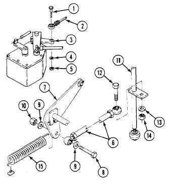
Install washer (4) and new locknut (5) on screw (1) and tighten.
10. Install link (6) on arm (7). Secure with screw (8), two washers (9) and new locknut (10).
11. Install link (6) on shaft (11). Secure with screw (12), washer (13) and new locknut (14).
12. Install spring (15) on arm (7) and bulkhead.
FOLLOW-THROUGH STEPS
1.
Adjust accelerator linkage (WP 0214 00).
2.
Install air intake elbow (WP 0173 00).
3.
Install power plant front access cover (WP 0449 00).
4.
Install driver’s compartment power plant access panel (see your -10).
5.
Close power plant front access door (see your -10).
6.
Raise trim vane (see your -10).
END OF TASK
0217 00-6