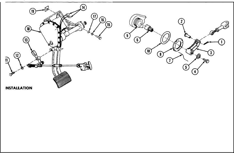
BRAKE ASSEMBLY IN DRIVER’S COMPARTMENT: REMOVAL, DISASSEMBLY, ASSEMBLY, INSTALLATION AND ADJUSTMENT
(CONTINUED)
A Install brake assembly (18) with shims (19) as required, four
screws (15), four new lockwashers (16) and four flat washers (17).
B
Connect two electrical connectors (14) to brake warning light
switch.
C
Install parking brake (13) with screw (11) and new lockwasher
(12).
D Position new seal (10) on support (9) and screw on retainer plate
(8).
E
Install new lockwire (7).
F
Install pull lever (3) on end of shaft (6) with screw (4) and flat
washer (5).
G Install straight pin (2) in pull lever (3) with new cotter pin (l).
H Close transmission access doors.
ADJUSTMENT
Refer to p 7-40 for instructions on adjustment of brake after
installation.
TA57218
7-17
Change 2
TM 9-2350-267-20

