6-60
TM 9-2350-267-20
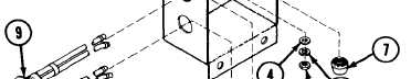
STACKER CONTROL SWITCH BOX:
REMOVAL, DISASSEMBLY, ASSEMBLY AND INSTALLATION (CONTINUED)
DISASSEMBLY
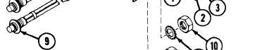
A Remove four screws (1), four nuts (2), four lockwashers (3)
and four flat washers (4).
B Remove receptacle (5) from box (6), unscrew retaining nut
(7) and pull rubber grommet (8) from receptacle (5).
C Push four pin sockets, on ends of switch (9) wires, from
receptacle (5).
D Remove rubber grommet (8) and retaining nut (7) from
switch (9) wires.
E Remove two switches (9) from box (6) by removing from
each one nut (10) and one lockwasher (11).
ASSEMBLY
NOTE
Seal all bare wires with silicone adhesive sealant
(item 5, Appx D).
A Locate pin sockets of switch (9) wires in receptacle (5) using
the following chart as a guide.
WIRE
PIN
NO
LOCATION
SWITCH
AAE
C
DOWN
10
D
AAD
I
A
I
UP
I
I
10
B
I
I
B
Reverse disassembly procedures.
INSTALLATION
Reverse removal procedures.
TA311091