TM 9 -2350-261-34
13.
14.
15.
16.
17.
18.
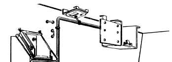
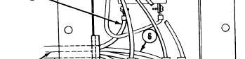
Thread battery cable (1) through rear
grommet (2) of junction box (3).
Connect circuit 6B POS lead (4) to rear ter-
minal of circuit breaker (5).
Connect circuit 7B NEG lead (6) to terminal
strip (7).
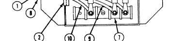
Thread alarm unit cable (8) through rear
grommet (2) of junction box (3).
Connect 509B lead (9) to terminal strip (7).
Connect 509C lead (10) to terminal
strip (7).
NOTE
Check wiring connections with wiring
diagram before attaching junction box.
19.
20.
21.
22.
23.
24,
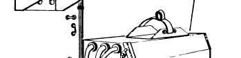
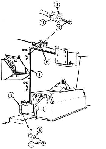
Remove two cap screws (11) and flat
washers (12) from hull.
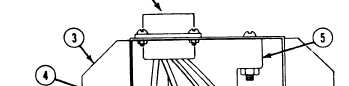
Place junction box (3) on hull. Secure with
two flat washers (12) and cap screws (11).
Tighten screws to 72-78 in-lb (8-9 N•m)
torque. Use torque wrench (item 109).
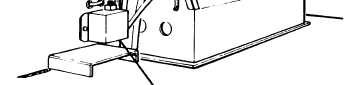
Remove two machine screws (13) from hull.
Place two new cradles (14) on hull. Secure
with two machine screws (13).
Remove two dome light lead cradle
clips (15).
Route alarm unit cable (8) over two
cradles (14) and along dome light lead.
Secure with two new cradle clips (16) and
dome light cradle clips (15).
23-4