TM 9-2350-261-20-1
R E P L A C E C O M P A R T M E N T T O B U L K H E A D F U E L H O S E S , T U B E S
A N D F I T T I N G S ( M 1 2 5 A 2 A N D M 1 0 6 A 2 O N L Y)
D E S C R I P T I O N
This task covers:
Remove (Page 6-81).
Install (Page 6-83).
I N I T I A L S E T U P
Tools:
General Mechanics Tool Kit (Item 30, App D)
Materials/Parts:
Sealing compound (Item 46, App C)
Wiping rag (Item 61, App C)
Self-locking nut
Self-locking nut (2)
Lockwasher (7)
Personnel Required:
Unit Mechanic
References:
See your –10
Equipment Conditions:
Engine stopped/shutdown (see your -10)
Carrer blocked (see your -10)
Ramp lowered (see your -10)
Battery g-round lead disconnected (page 13-2)
Power plant rear access panel removed
(page 24-29)
Fuse stowage racks removed (page 24-186)
Floor plates removed (page 24-38)
Fuel compartment drained (page 6-77)
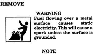
Use wiping rag to wipe up any spilled fuel.
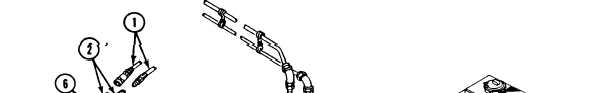
1. Separate two quick-disconnect fittings
(1 and 2) inside power plant rear bulkhead.
2.
3.
4.
5.
6.
Disconnect fuel supply hose (3) and fuel re-
turn hose (4) from two nipples (5).
N O T E
Tag quick disconnect couplings before
removal.
Remove two quick-disconnect fittings (2) from
two elbows (6).
Remove two elbows (6) from two tube
assemblies (7).
Remove two tube assemblies
nipples (5).
Remove two nipples (5) from
(7) from two
transverse
beam.
GO TO NEXT PAGE
6-81