TM 9-2350-261-20-1
2 0 0 A M P O V E R V O L T A G E T R O U B L E S H O O T I NG
INITIAL SETUP
Tools:
References:
General Mechanic’s Tool Kit (Item 30, App D)
See your -10
Multimeter (Item 43, App D)
TM 9-6140-200-14
Electrical Connector Pliers (Item 44, App D)
AlternatorTest Kit (Item 74.1, App D)
Equipment Conditions:
Engine stopped (see your -10)
Personnel Required:
Carrier blocked (see your -10)
Unit Mechanic
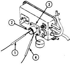
1. Turn MASTER SWITCH ON.
2. Measure battery voltage by placing red lead (1) in posi-
tive socket of NATO plug (2) on auxiliary power (slave)
receptacle (3). Touch black negative lead (4) to outside
of NATO plug on receptacle.
NOTE
On earners that have standard auxiliary
power receptacles, touch red lead to
positive and black lead to negative
sockets in the receptacle.
3. Adjust voltage regulator (200 amp) to lowest setting
(page 9-38).
4. Start engine and accelerate.
5. Does voltage climb to 32 to 34 volts and suddenly drop
to battery voltage?
GO TO PAGE 344.13
Change 1
3-64.11