TM 9-2350-261-20-1
E N G I N E C R A N K S S L O W L Y
INITIAL SETUP
Tools:
General Mechanics Tool Kit (Item 30, App D)
Digital Multimeter (Item 43, App D)
STE/ICE-R Test Set (Item 71.1, App D)
Personnel Required:
Unit Mechanic
Helper (H)
References:
See your -10
STE/ICE-R starter circuit troubleshooting
(page 3-259)
Equipment Conditions:
Engine stopped/shutdown (see your -10)
Carrier blocked (see your -10)
Trim vane lowered (see your -10)
Power plant access door open (see your -10)
1. Remove cover (1) from auxiliary power receptacle (2).
2. Turn MASTER SWITCH to ON (see your -10).
3. Measure voltage between positive (+) terminal (3) and
negative (-) terminal (4) with engine cranking for 3 to 5
seconds.
4. Does multimeter read more than 19 volts?
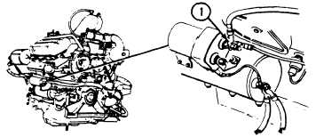
1. Measure voltage between starter positive (+) terminal
(1) and ground with engine cranking for 3 to 5 seconds.
2. Does multimeter read more than 17 volts?
GO TO NEXT PAGE
GO TO NEXT PAGE
GO TO PAGE 3-27
Change 1 3-25