
TM 9-2350-247-20-2
REPLACE CIRCUIT BREAKER
THIS WORK PACKAGE COVERS:
Removal (page 0267 00-1).
Installation (page 0267 00-1).
INITIAL SETUP:
Maintenance Level
Equipment Condition
Unit
Engine stopped (see your -10)
Carrier blocked (see your -10)
MASTER SWITCH OFF (see your -10)
Tools and Special Tools
Instrument panel partially removed (WP 0256 00)
General Mechanic's Tool Kit (WP 0541 00, Item 57)
Personnel Required
Unit Mechanic
References
See your -10
REMOVAL
NOTE
Instrument panel switches, indicators, and controls will vary between the M548A1 and
M548A3. M548A1 instrument panel is shown.
1.
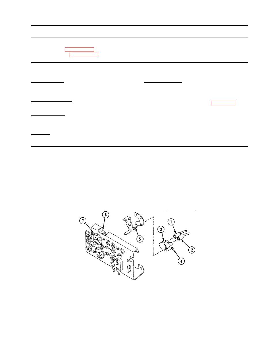
Disconnect circuit 10 lead (1) and circuit 27 lead (2) from circuit breaker (3).
2.
Remove two nuts (4) and screws (5) that secure circuit breaker (3) to bracket mount (6) on back of speedometer (7).
Remove circuit breaker (3) from bracket mount (6).
INSTALLATION
1.
Place circuit breaker (3) on bracket mount (6) on back of speedometer (7). Secure with two screws (5) and nuts (4).
2.
Connect circuit 27 lead (2) and circuit 10 lead (1) to circuit breaker (3).
