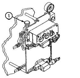
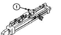
CONVEYOR SPEED ADJUSTMENTNOTE• Flow-control valve on hydraulic controlpanel regulates operating speed of theconveyor. Flow-control valve is manuallyadjustable.• Do not let pressure rise to above 800 psi,or APU generator will not operate.flow-flow-1. To increase speed of conveyor, turncontrol valve (1) counterclockwise.2. To decrease speed of conveyor, turncontrol valve (1) clockwise.UPPER REAR DOOR FLOW-CONTROL VALVEADJUSTMENTWARNINGNever operate upper rear door until door-travel area is clear of personnel. Doormay strike personnel, causing severeinjury.NOTEThe upper rear door is most prone toerratic operation during the first threeseconds of closing. This valve is designedto smooth door closing.To adjust:1. Activate hydraulic system (p. 2-131).2.Open upper rear door (p. 2-138).3. Turn flow-control valve (1) counterclockwiseuntil fully open.4.While closing door (p. 2-140), slowly turn flow-control valve (1) clockwise until door closessmoothly.5. Open door (p. 2-138) and repeat step 4.Continue to operate and adjust flow-controlvalve (1) until dooroperates smoothly for entireclosing cycle.TM 9-2350-287-10Change 13-39
Integrated Publishing, Inc. - A (SDVOSB) Service Disabled Veteran Owned Small Business