|
| |
TM 9-2350-287-34
7-2.
FINAL DRIVE ASSEMBLY REPAIR (continued).
8.
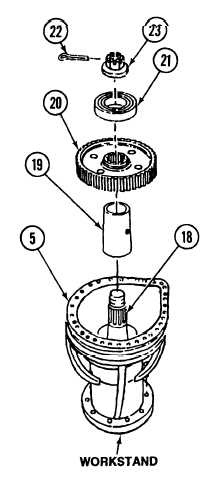
Install bearing (21) on ring gear (20).
9.
With the aid of an assistant, place housing (5) in final drive workstand.
10.
Install spacer (19) and ring gear (20) on output shaft (18).
11.
Install nut (23) on output shaft (18).
CAUTION
To prevent nut from backing off output shaft and causing severe damage to equipment,
the following torquing procedure must be followed.
12.
a. Torque nut (23) between 450 and 475 ft-lb.(610 and 643 N•m).
b. If slot in nut (23) is alined with cotter-pin hole in output shaft (1 8), go to step 13.
c. If slot in nut (23) is not alined with cotter-pin hole in output shaft (1 8), continue to torque nut (23) (maximum
30 ft-lb., or 41 N•M until next slot is alined, then go to step 13.
13.
Install new cotter pin (22) in nut (23).
7-7
|