|
| |
TM 9-2350-287-34
6-3. STE/lCE RESISTOR BOX REPAIR (continued).
2.
3.
4.
c.
1.
2.
3.
4.
5.
6.
7.
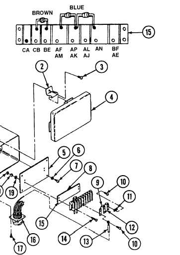
Inspect terminal board (15) and panel (5)
for cracks or breaks. Replace defective
parts as necessary.
Inspect five terminal lugs (12) and three
fixed resistors (9) for cracked or broken
lugs.
Secure terminal board (15) and marker strip (8) to panel (5) with four screws (14), washers
Iockwashers (20), and nuts (21).
(19), new
Install panel (5), with terminal board (15), in box housing (1) with four screws (7) and new Iockwashers (6).
Install five terminal lugs (12) and three fixed resistors (9) and bus connectors (11) on terminal board (15) with
eight terminal screws (10).
Install 12 terminal leads (13) on terminal board (15) with eight terminal screws (10).
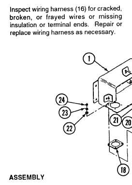
Install new gasket (18) and wiring harness (16) in box housing (1) with four screws (17), washers (22), new
Iockwashers (23), and nuts (24).
Install cover (4) on box housing (1) and hook four retainers (2) to secure
Install four screws (3) in four retainers (2).
FOLLOW-ON MAINTENANCE:
• None
6-13
|