|
| |
TM 9-2350-287-20-2
11-10. TRACK ADJUSTER AND MOUNTING BRACKET REPLACEMENT (continued).
3.
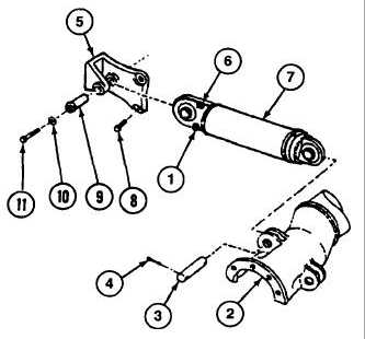
Remove screw (11 ) and washer (10) from
mounting bracket (5).
4.
Install new capscrew and washer in pivot pin (9).
5.
Using mechanical puller, remove capscrew,
washer, pivot pin (9), and track adjuster (7) from
mounting bracket (5). Remove capscrew and
washer from pivot pin (9).
6.
Remove two screws (8) and mounting bracket
(5) from hull.
7.
Remove bleed plug (1) and lubrication fitting (6)
from track adjuster (7).
b.
INSTALLATION
1.
Apply antiseizing tape to threaded portion of bleed plug (1).
2.
Install bleed plug (1) and lubrication fitting (6) on track adjuster (7).
3.
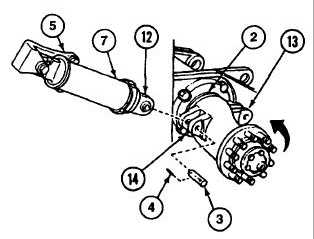
Add grease to track adjuster (7) through lubrication fitting (6) until piston (12) is extended 1/2 to 1 inch.
4.
Install mounting bracket (5) on hull with two screws (8), and torque screws between 360 and 420 ft-lb (488 and
570 N
m).
NOTE
An assistant is needed to hold track adjuster in place during installation of pins.
5.
Position track adjuster (7) in mounting bracket (5) and idler arm assembly (2).
6.
Install pivot pin (9) in mounting bracket
(5).
7.
Install pin (3) in lug hole (13) in idler arm
assembly
(2).
Rotate
idler
arm
assembly (2) counterclockwise with pry
bar to align track adjuster (7) with lug
hole (14).
8.
Remove pin (3) from lug hole (13).
9.
Install pin (3) and two new cotter pins
(4) in idler arm assembly (2).
10.
Install screw (11) and washer (10) in
pivot pin (9). Torque screw between
300 and 350 ft-lb (407 and 475 N
m).
FOLLOW-ON MAINTENANCE:
Install track (para 11-14).
Change 1 11-24
|