|
| |
TM 9-2350-287-20-2
11-10. TRACK ADJUSTER AND MOUNTING BRACKET REPLACEMENT.
This Task Covers:
a. Removal
b. Installation
Initial Setup:
Tools/Test Equipment:
Grease (Item 33, Appendix D)
Puller, mechanical
Rag (Item 56, Appendix D)
(Item 38, Appendix B)
Tape, antiseizing (Item 70, Appendix D)
Crowbar (Item 12, Appendix I)
Washer (Item 76, Appendix D)
General mechanic's tool kit
Cotter pin (2) (Item 33, Appendix H)
(Item 24, Appendix I)
Socket wrench extension, 16-inch
Personnel Required: Two
(Item 56, Appendix I)
Socket wrench socket, 1 1/8-inch
Equipment Conditions:
(Item 60, Appendix I)
Vehicle parked on level ground (refer to
Torque wrench, 0-600 ft-lb
TM 9-2350-287-10).
(Item 70, Appendix I)
Track removed (para 11-14).
Materials/Parts:
Capscrew (Item 12, Appendix D)
a.
REMOVAL
WARNING
Lubricant is under high pressure. Loosen bleed plug slowly to avoid injury.
NOTE
· Replacement is the same for left
and right track adjusters and
mounting
brackets.
Left
adjuster is shown in illustration.
· If removing bleed plug or
lubrication fitting only, go to
step 7.
1.
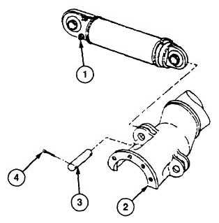
Loosen bleed plug (1).
2.
Remove two cotter pins (4) and pin (3)
from idler arm assembly (2). Discard
cotter pins.
Change 1 11-23
|

