|
| |
TM 9-2350-287-20-2
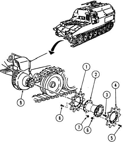
11-11. FINAL DRIVE SPROCKET AND HUB REPLACEMENT.
This Task Covers:
a. Removal
b. Installation
Initial Setup:
Tools/Test Equipment:
• General mechanics tool kit
(Item 24, Appendix I)
• Socket extension, 8-inch, 3/4-inch drive
(Item 55, Appendix I)
l Socket wrench, 1-inch, 3/4-inch drive
(Item 58, Apendix I)
• Torque wrench, 0-175 ft-lb
(Item 69, Appendix I)
l Torque wrench, 0-600 ft-lb, 3/4-inch drive
(Item 70, Appendix I)
Materials/Parts:
• Self-locking screw (8) (Item 301, Appendix H)
l Self-locking nut (20) (Item 327, Appendix H)
Personnel Required: Two
Equipment Conditions:
• Vehicle parked on level ground (refer to
TM 9-2350-287-10).
• Track disconnected (para 11-14).
a.
REMOVAL
Hub is very heavy. To
prevent injury, at least two
people are needed when
removing hub.
NOTE
Hub with inner and outer
sprockets attached may be
removed as an assembly
by removing eight screws.
1.
Remove 10 self-locking nuts (6)
and screws (5) and outer sprocket
(4) from hub (2). Discard self-
Iocking nuts.
2.
Remove eight self-locking screws
(3) from hub (2). Insert two self-
Iocking screws (3) in hub pilot
holes. Tighten to pull hub (2) and
inner sprocket (1 ) away from drive
assembly (9). Discard six self-
Iocking screws.
11-25
WARNING
|