|
| |
18-4.
APU ENGINE SUPPORT STAND AND SUPPORT ASSEMBLY REPLACEMENT
(continued).
7.
8.
b.
1.
2.
3 .
4.
5.
6.
7.
8.
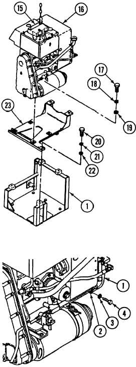
Personnel must stand clear during lifting
cause severe injury.
operations. A swinging or shifting load can
Remove four screws (20), lockwashers (21), and
washers (22). Using hoist, lift APU from support
stand (1). Discard Iockwashers.
Remove four screws (17), Iockwashers (18), and
washers (19) and support assembly (23) from
APU. Discard Iockwashers.
INSTALLATION
Install support assembly (23) on APU using four
washers (19), new Iockwashers (18), and screws
(17).
Attach lifting clevis (16) to APU lifting eye plate
(15) and attach suitable hoist to clevis.
Using hoist, install APU on support stand (1).
Secure APU to support stand (1) with four
washers (22), new Iockwashers (21), and screws
(20).
Connect electrical lead 66 (11) to generator (10).
Connect ground Iead connector (12) to generator
(10).
Install electrical harnesses (5) on support stand
(1) using clamp (6), washer (7), new Iockwasher
(8), and screw (9).
Connect two electrical connectors (13) to hour
meter (14).
Install clamp (2), new Iockwasher (3), and screw
(4) on APU support stand (1).
FOLLOW-ON MAINTENANCE:
• Install APU (para 18-2).
• Install APU generator air duct (para 18-17).
10-11
TM 9-2350-287-20-2
|