|
| |
TM 9-2350-287-20-2
17-15. IDLER SPROCKET ASSEMBLY REPLACEMENT (continued).
b.
INSTALLATION
1.
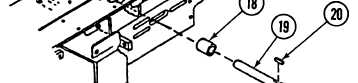
Install hub (16) and key (20) on shaft (19).
2.
3.
4.
5.
6.
7.
8.
Position sprocket assembly (15) on shaft (19) but do not secure to hub (16). Position spacer (18) on shaft (19).
Install shaft (19), with spacer (18) and sprocket assembly (15) installed, on shaft (19) in takeup-end section
(6).
Install
Install
sprocket assembly (15) on hub (16) with two screws (17). Do not tighten screws.
spacer (14) on shaft (19).
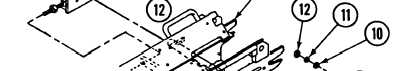
Install two takeup plates (7) on takeup-end section (6) with two nuts (13).
Insert ends of shaft (19) through two takeup plates (7).
Install two takeup plates (7) to takeup-end section (6) with six screws (8), new Iockwashers (11), washers (9),
washers (10), and two nuts (12).
17-38
|