|
| |
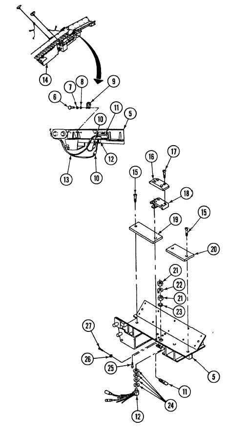
17-8. DEAD-END SECTION ASSEMBLY REPAIR (continued).
3.
4.
5.
Disconnect two ground leads
(10) from override safety
switch (11) and deadman
switch (12) on rear dead-end
section assembly (5).
Remove three screws (6),
Iockwashers (7), washers (8),
straps (9) and conveyor
electrical wiring harness (13)
from rear dead-end section
assembly (5).
Discard
Iockwashers.
Remove either dead-end
section assembly (1 or 5) from
adjoining conveyor section
(14).
b.
DISASSEMBLY
NOTE
Steps 1 through 5 apply only to rear dead-end
sect ion.
1.
2.
3.
4.
5.
Remove two screws (27) and Iockwashers (26) and
override safety switch (11) from rear dead-end section
assembly (5). Discard Iockwashers.
Remove four screws (25) and moving bracket (18)
from rear dead-end section assembly (5).
NOTE
Perform step 3 only if wear strip is damaged.
Remove four screws (17) from wear strip (16), and
remove wear strip (16) from moving bracket (18).
Remove two nuts (21), key washer (22), Iockwasher
(23), four washers (24) and deadman switch (12)
from rear dead-end section assembly (5).
Remove fourscrews (15) and two wear strips(19 and
20) from rear dead-end section assembly (5).
17-14
|