|
| |
TM 9-2350-287-20-2
17-8. DEAD-END SECTION ASSEMBLY REPAIR.
This Task Covers:
a. Removal
b. Disassembly
c. Assembly
d. Installation
Initial Setup:
Tools/Test Equipment:
l General mechanic’s tool kit (Item 24,
Appendix l)
Materials/Parts:
l Adhesive, rubber (Item 4, Appendix D)
l Sealing compound (Item 58, Appendix D)
l Cotter pin (2) (Item 18, Appendix H)
l Cotter pin (4) (Item 29, Appendix H)
l Lockwasher (2) (Item 120, Appendix H)
l Lockwasher (2) (Item 158, Appendix H)
l Lockwasher (2) (Item 160, Appendix H)
l Lockwasher (3) (Item 196, Appendix H)
l Rubber strip (Item 253, Appendix H)
Equipment Conditions:
l Vehicle parked on level ground (refer to
TM 9-2350-287-10).
l Conveyor deployed (refer to
TM 9-2350-287-10).
l MASTER switch set to OFF (refer to
TM 9-2350-287-10).
a.
1.
2.
REMOVAL
NOTE
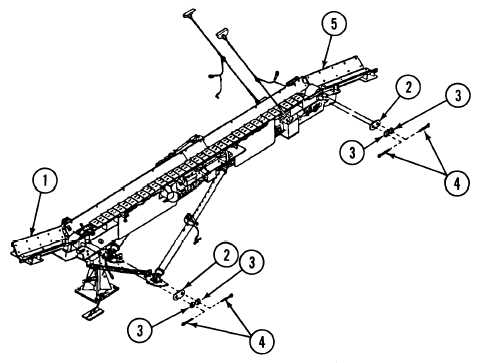
Steps 1,2, and 5 apply to both the forward and the rear dead-end section assemblies
of the conveyor. Steps 3 and 4 apply only to the rear dead-end section assembly.
Fold up rear dead-end section assembly (5) or forward dead-end section assembly (1).
Remove four cotter pins (4) and washers (3) and two connecting links (2) from either dead-end section
assembly (1 or 5). Discard cotter pins.
17-13
|