|
| |
TM 9-2350-287-20-2
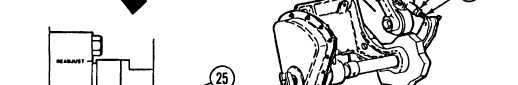
10-3. POWERPACK COMPARTMENT BRAKE LINKAGE REPLACEMENT/ADJUSTMENT
(continued).
f.
1.
2.
3.
4.
5.
6.
7.
ADJUSTMENT
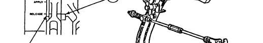
With brake pedal fully raised, check for slack in chain (22) and alinement of brake lever index marks (25)
with release mark (26). If index marks are alined, no adjustment is necessary.
Remove cotter pin (4) and pin (5) from lever (8). Discard cotter pin.
Loosen nut (20) on rod end (21).
Rotate rod end (21) until all slack is removed from chain (22), holes in rod end (21) and lever (8) are alined,
and brake lever index marks (25) are at release mark (26).
Install pin (5) and new cotter pin (4) on lever (8).
Check release marks (26) for alinement with brake lever index marks (25).
Tighten nut (20) against rod end (21).
FOLLOW-ON MAINTENANCE:
• Close transmission doors (refer to TM 9-2350-287-10).
• Adjust stoplight switch (para 7-20).
10-9
|