|
| |
TM 9-2350-287-20-2
10-4. DRIVER’S COMPARTMENT BRAKE ASSEMBLY REPAIR.
This task covers:
a. Removal
b. Disassembly
c. Cleaning and Inspection
d. Assembly
e. Installation
f. Adjustment
Initial Setup:
Tools/Test Equipment:
• General mechanic’s tool kit (Item 24,
Appendix I)
• Snapring pliers (Item 53, Appendix I)
Materials/Parts:
• Drycleaning solvent (Item 28, Appendix D)
• Rag (Item 56, Appendix D)
• Boot (Item 5, Appendix H)
• Cotter pin (2) (Item 17, Appendix H)
• Cotter pin (Item 24, Appendix H)
• Gasket (Item 95, Appendix H)
• Lockwasher (4) (Item 175, Appendix H)
• Lockwasher (4) (Item 177, Appendix H)
• Lockwire (Item 202, Appendix H)
• Retaining ring (Item 244, Appendix H)
• Seal (Item 269, Appendix H)
• Seal (Item 293, Appendix H)
• Self-locking nut (10) (Item 312, Appendix H)
• Self-locking nut (3) (Item 315, Appendix H)
• Self-locking nut (Item 330, Appendix H)
a.
REMOVAL
1.
2.
3.
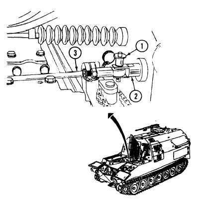
Remove quick-release pin (1) and
disconnect shift linkage (3) from
rod (2).
Remove cotter pin (10), straight
pin (7), and lever (8) from rod end
bearing (9). Discard cotter pin.
Remove screw (1), washer (12),
and lever (8) from shaft (5).
Equipment Conditions:
• Vehicle parked on level ground (refer to
TM 9-2350-287-10).
• Track blocked (refer to TM 9-2350-287-10).
• Left and right transmission access doors opened
(refer to TM 9-2350-287-10).
• Parking brake light switch and bracket removed
(para 7-20).
• Center driver's periscope removed
(refer to TM 9-2350-287-10).
10-10
|