Order this information in Print

Order this information on CD-ROM

Download in PDF Format


Click here to make tpub.com your Home Page

Page Title: e. INSTALLATION
Back | Up | Next

Click here for a printable version

Google


Web
www.tpub.com

Home


Information Categories
.... Administration
Advancement
Aerographer
Automotive
Aviation
Combat
Construction
Diving
Draftsman
Engineering
Electronics
Food and Cooking
Math
Medical
Music
Nuclear Fundamentals
Photography
Religion
USMC
   
Products
  Educational CD-ROM's
Printed Manuals
Downloadable Books


TM 9-2350-287-20-2 10-3. POWERPACK COMPARTMENT BRAKE LINKAGE REPLACEMENT/ADJUSTMENT _ (continued). 3. 4. 5 e. 1. 2. 3. 4. 
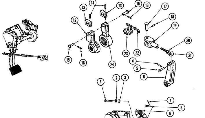
Position two clevises (13) in place on left brake lever (12) and right brake lever (24) and secure with two pins (15) and new cotter pins (16). Install sprocket (23) and chain (22) in clevis(19) and secure with pin (17) and new cotter pin (18). Screw rod end (21) in clevis (19). INSTALLATION 
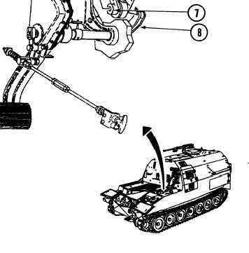
Position    powerpack    compartment brake linkage (6) in place on shaft (7). Install screw (1), new Iockwasher (2), and washer (3) in shaft (7). Install rod end (21 ) in lever (8) and secure with pin (5) and new cotter pin (4). 
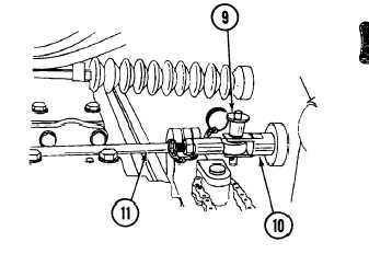
Connect shift linkage (11 ) to rod (10) and install quick-release pin (9). 10-8

Privacy Statement - Press Release - Copyright Information. - Contact Us - Support Integrated Publishing

Integrated Publishing, Inc. - A (SDVOSB) Service Disabled Veteran Owned Small Business