|
| |
TM 9-2350-287-20-2
10-3. POWERPACK COMPARTMENT BRAKE LINKAGE REPLACEMENT/ADJUSTMENT.
This task covers:
a. Removal
b. Disassembly
c. Cleaning and Inspection
d. Assembly
e. Installation
f. Adjustment
Initial Setup:
Tools/Test Equipment:
• GeneraI mechanic’s tool kit (Item 24,
Appendix I)
Materials/Parts:
• Drycleaning solvent (Item 28, Appendix D)
• Rag (Item 56, Appendix D)
• Cotter pin (4) (Item 17, Appendix H)
• Lockwasher (Item 176, Appendix H)
• Spring pin (2) (Item 367, Appendix H)
Equipment Conditions:
• Vehicle parked on level ground
(refer to TM 9-2350-287-10).
• Parking brake released (refer to
TM 9-2350-287-10).
• Transmission doors opened (refer to
TM 9-2350-287-10).
• Track blocked (refer to TM 9-2350-287-10).
a.
1.
2.
3.
4.
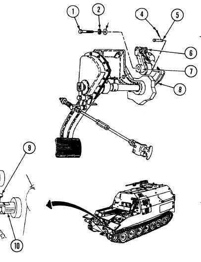
REMOVAL
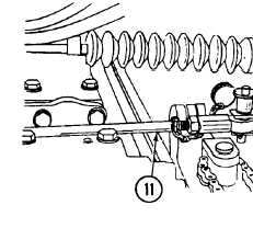
Remove quick-release pin (9) and
disconnect shift linkage (11) from rod
(10).
Remove cotter pin (4) and pin (5) from
lever (8) and disconnect powerpack
compartment brake linkage (6) from
lever (8). Discard cotter pin.
Remove Screw (1), Iockwasher (2), and
washer (3) from shaft (7). Discard
Iockwasher.
Remove powerpack compartment
brake linkage (6) from shaft (7).
10-6
|