TM 9-2350-287-20-1
7-9. DRIVER’S INSTRUMENT PANEL REPAIR (continued).
b.
1.
2.
3.
4.
5.
6.
7.
8.
9.
c.
1.
2.
3.
DISASSEMBLY
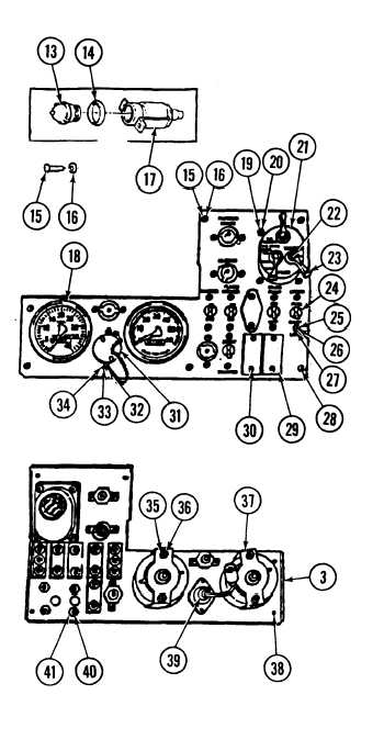
Remove four lenses (13) and preformed packings
(14) from front of instrument panel (3).
Remove eight screws (15) and Iockwashers (16)
and four light brackets (17) from instrument
panel (3). Discard Iockwashers.
Remove 10 screws (25), Iockwashers (26), and
washers (27) and five switch assemblies (24)
from instrument panel (3). Discard Iockwashers.
Remove four nuts (35) and Iockwashers (36) and
two brackets (37) and indicators (18) from
instrument panel (3). Discard Washers.
Remove three screws (22), handles (23), and
spacers (hidden) from light switch (21 ).
Remove four screws (19) and Iockwashers (20)
and light switch (21 ) from instrument panel (3).
Remove cover (31 ), two screws (32), washers
(33), and Iockwashers (34), and auxiliary outlet
(39) from instrument panel (3). Discard
Iockwashers.
NOTE
Some instrument panels are equipped with
only one cover plate.
Remove six nuts (41), lockwashers (40), screws
(30), and three cover plates (29) from instrument
panel (3).
Remove six stud turn locks (28) and split washers
(38) from instrument panel (3). Discard split
washers.
ASSEMBLY
Install six new split washers (38) and stud turn locks (28) on instrument panel (3).
Install three cover plates (29) and six screws (30), new Iockwashers (40), and nuts (41) on instrument panel
(3).
Install auxiliary outlet (39), two new Iockwashers (34), washers (33), and screws (32), and cover (31) on
instrument panel (3).
7-26