TM 9-2350-287-20-1
3-3
GROUND HOP PROCEDURES
This Task Covers:
a.
Installation
b.
Operating Procedures
c.
Removal Procedures
Initial Setup:
Tools/Test Equipment:
Safety screen (Item 50, Appendix I)
Electrical power cable assembly 12268427
STE/ICE test equipment (Item 65, Appendix I)
(Item 17, Appendix I)
Electrical power cable assembly 12268162
Materials/Parts:
(Item 18, Appendix I)
Exhaust pipe 12260213-1 (removed from
Electrical power cable assembly 12268426
vehicle)
(Item 19, Appendix I)
Lockwasher (2) (retained from powerpack)
General mechanic's tool kit (Item 24,
Appendix I)
Equipment Conditions:
Ground cable assembly (Item 25,
Powerpack removed (para 3-2).
Appendix I)
Hose assembly (2) (Item 29, Appendix I)
Personnel Required: Two
Protective screen assembly (2)
(Item 45, Appendix I)
References:
Quick-disconnect coupling (Item 46, Appendix I)
TM 9-4910-571-12&P
a.
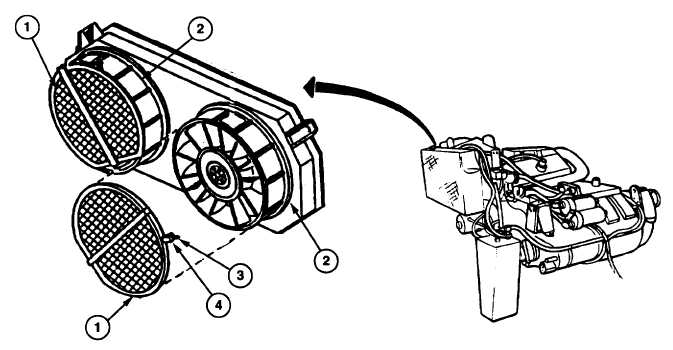
INSTALLATION PROCEDURES
1.
Install protective fan screen (1) on each of two radiator fans (2) with two thumbscrews (3) and nuts (4).
Change 1 3-16