TM 9-2350-287-20-1
2-19. TROUBLESHOOTING CHART (continued).
Initial Setup:
Tools/Test Equipment:
l Engine AFES Test/Alarm panel MAINT switch in
l Digital multimeter (DMM) (Item 13, Appendix I)
maintenance position (para 21 -2).
l General mechanic’s tool kit (Item 24,
Appendix I)
Equipment Conditions:
l Left projectile rack moved to rear of vehicle
(refer to TM 9-2350-287-10).
NOTE
l Instead of using multi meter
for voltage check, STE/lCE
troubleshooting,
INDIVIDUAL
BATTERY VOLTAGE TEST-TEST
89 maybe performed.
l Instead of using multi meter
for continuity check, STE/lCE
troubleshooting, TEST 91 may be
performed.
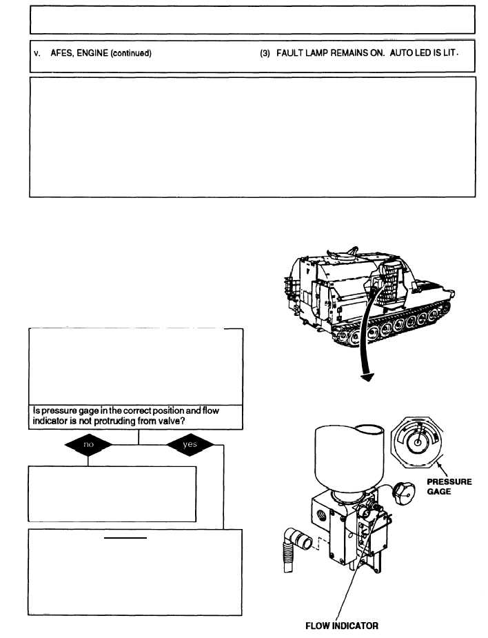
A. 1. Check for protruding flow indicator of
valve actuator of engine fire extinguisher
no. 1.
2. Check pressure gage of engine fire ex-
tinguisher no. 1 and make sure black needle
is on green temperature wedge.
If flow indicator is protruding, reset flow
indicator of valve actuator by pushing into
valve body. If pressure is low, replace
engine extinguisher no. 1. Verify problem
is solved.
B.
WARNING
Make sure that engine T/A panel
Maintenance switch is in the
vertical position. Failure to comply
may result in cylinder discharge.
Continued to next page
2-331