TM 9-2350-287-20-1
2-19. TROUBLESHOOTING CHART (continued).
v. AFES, ENGINE (continued).
(2) FIRE WIRE (F/W) LED REMAINS ON, NO FIRE
PRESENT
Initial Setup:
Tools/Test Equipment:
Forward battery box open
Digital multimeter (Item 13, Appendix I)
(refer to TM 9-2350-287-10).
General mechanic's tool kit (Item 24,
Air intake grille opened and secure
Appendix I)
(refer to TM 9-2350-287-10).
Engine AFES test and alarm panel MAINT switch
Materials/Parts:
in maintenance position (para 21-2).
Cleaning compound (Item 14, Appendix D)
Equipment Conditions:
Transmission doors open
(refer to TM 9-2350-287-10).
A.
CAUTION
Digital multimeter (DMM) must not be
operated any longer than necessary to
obtain a reading. Misleading improvements
in resistance readings could result.
NOTE
·Use a DMM for the following tests. Do not
use a standard volt/ohm meter (VOM).
The VOM's method of operation will not
give accurate readings.
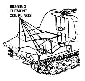
·Sixty-inch elements are installed at the
underside of engine deck, above engine.
1. Disconnect all fire sensing element couplings (para 21-10).
2. Check all connections for dirt and grease. Clean with
cleaning compound.
3. Using a multimeter, measure resistance between center
and outer sheath of each of five sensing elements and six
couplings separately.
4. Resistance of each item must be greater than 1 megohm.
Are any components defective?
Continued on next page
Change 1 2-328