TM 9-2350-287-20-1
2-19. TROUBLESHOOTING CHART (continued).
u. AUXILIARY POWER UNIT (continued).
(1) ENGINE CRANKS BUT FAILS TO START
(continued).
I
CONTINUED FROM G
CONTINUED AT STEP K
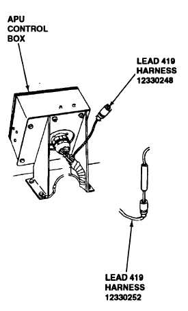
H. 1. Reconnect wire harness 12330248 plug to
APU control box.
2. Install APU control box (para 7-22).
3. Disconnect lead 419 shell connectors where
harnesses 12330248 and 12330252 connect.
4. Place red probe of multimeter in lead 419
shell connector of wire harness 12330252 and
ground black lead.
5. With the aid of an assistant turn MASTER
switch ON (refer to TM 9-2350-287-10).
6. Check for 24 ± 3 vdc.
7. Turn MASTER switch OFF (refer to TM 9-
2350-287-10).
Is voltage indicated?
Repair lead 419 or replace harness
12330248 (para 7-71) Verify problem is
s o l v e d .
1. 1. Reconnect lead 419 of wire harness
12330252 to lead 419 of wire harness
12330248.
2. Disconnect lead 419 from circuit breaker
No. 8 output of circuit breaker panel no. 1
Continued on next page
2-296