TM 9-2350-287-20-1
2-19. TROUBLESHOOTING CHART (continued).
h. LIGHTS (continued).
(18) ACCESSORY CONTROL BOX PANEL LIGHTS
FAIL TO OPERATE. All other Iights operate.
Initial Setup:
Tools/Test Equipment:
Digital multimeter (DMM) (Item 13, Appendix I
General mechanics tool kit (Item 24,
Appendix I)
Equipment Conditions:
MASTER switch set to OFF (refer to TM
9 - 2 3 5 0 - 2 8 7 - 1 0 ) .
Lighting switch selector set to PANEL
LIGHTS (refer to TM 9-2350-287-10).
NOTE
Instead of using multi meter
for voltage
check, STE/lCE
troubleshooting,
INDIVIDUAL
BATTERY VOLTAGE TEST-TEST
89 maybe performed.
. Instead of using multimeter
for continuity check, STE/lCE
troubleshooting, TEST 91 may
be performed.
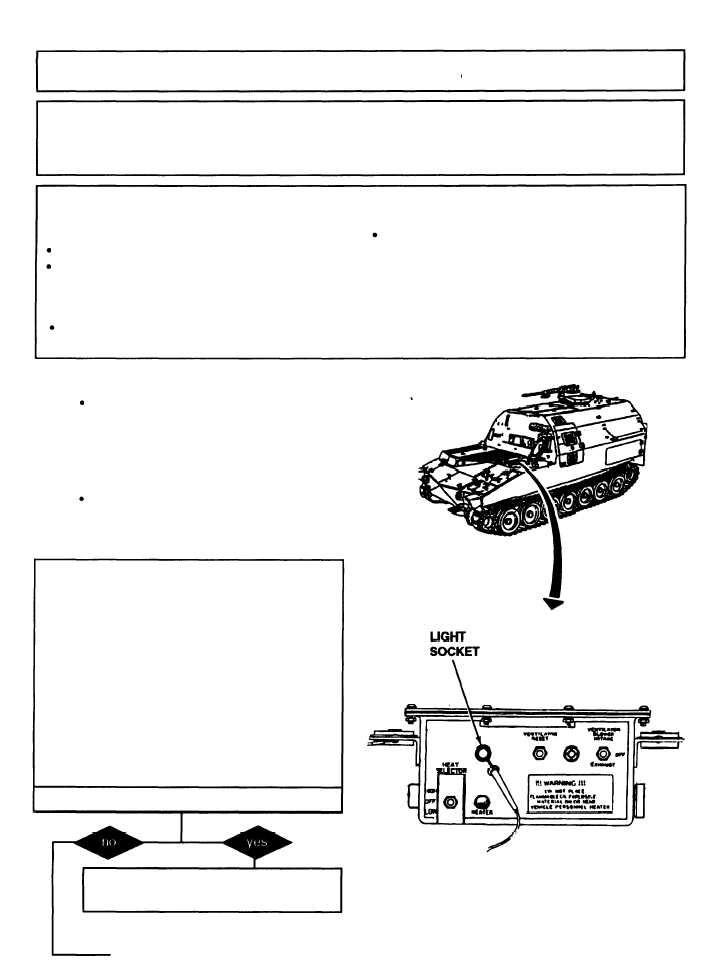
A.
1. Remove panel light from acessory control
box.
2. Place multimeter red lead in center contact
of light bulb socket and ground black lead.
3. Turn MASTER switch ON (refer to TM 9-
2350-287-10).
4. Check for 24 ± 3 vdc.
5. Turn MASTER switch OFF (refer to TM 9-
2350-287-10).
Is voltage indicated?
Replace light bulb (para 7-10). Verify
problem.
Continued on next page
2-189