TM 9-2350-287-20-1
2-19. TROUBLESHOOTING CHART (continued).
h. LIGHTS (continued).
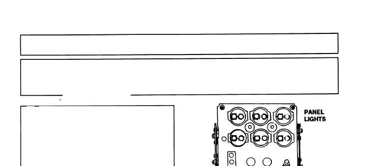
(17) PORTABLE INSTRUMENT PANEL LIGHTS FAIL
TO OPERATE. All other lights operate (continued).
B.
1. Remove front panel of driver’s portable
instrument panel.
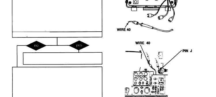
2. Disconnect lead 40 at light socket.
3. Place red lead of multimeter in lead 40
and ground black lead.
4. Turn MASTER switch ON (refer to TM 9-
2350-287-10).
5. Check for 24 ± 3 vdc.
6. Turn MASTER switch OFF (refer to TM 9-
2350-287-10).
CONTINUED FROM A
Is voltage indicated?
Replace instrument panel light socket (para
7-6). Verify problem is solved.
C. 1. Disconnect harness 12260298 connector
from harness 12260287.
2. Place one lead of multimeter on pin J of
connector and place other lead of multimeter
in wire 40 lamp connector.
3. Check for continuity.
4. Repeat steps 2 and 3 for other wire 40
lamp connector.
Is continuity indicated in both circuits?
Repair or replace harness 12260298 (para
7-7). Verify problem is solved.
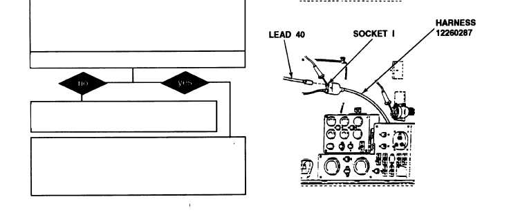
D. 1. Install front panel of driver’s portable in-
strument panel.
2. Disconnect harness 12260298 lead 40
from Y connector.
Continued on next page
2-196


