TM 9-2350-287-20-1
2-19. TROUBLESHOOTING CHART (continued).
d. ENGINE, ELECTRICAL SYSTEM (continued).
(4) ONE OR MORE GLOW PLUGS FAIL TO
OPERATE.
Initial Setup:
Tools/Test Equipment:
Equipment Conditions:
• Digital multimeter (DMM) (Item 13, Appendix 1)
l MASTER switch set to OFF (refer to
• General mechanic’s tool kit (Item 24,
(TM 9-2350-287-10).
Appendix 1)
l Open engine intake grille (refer to
(TM 9-2350-287-10).
Personnel Required: Two
NOTE
l Instead of using multimeter for voltage
check, STE/iCE troubleshooting,
INDIVIDUAL BATTERY TEST-TEST
89 maybe performed.
l Instead of using multi meter
for continuity check, STE/lCE
troubleshooting, TEST 91 may
be performed.
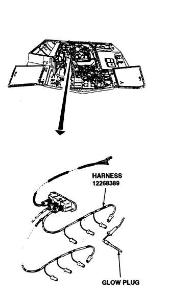
A. 1. Disconnect wire harness 12268389 from
suspect glow plugs.
2. Place positive end of circuit tester to posi-
tive batterty terminal.
3. Touch probe end of 24V circuit tester to
suspect glow plug.
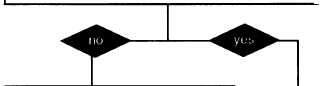
Does circuit tester light up when 24V circuit tester is
applied?
Replace glow plugs (para 4-27).
Verify problem is solved
I
NOTE
Glow plug system will only operate
when temperature is 50°or less.
It can be tricked into operating by
placing an ice bag on the controller.
Continued on next page
2-72