TM 9-2350-277-34
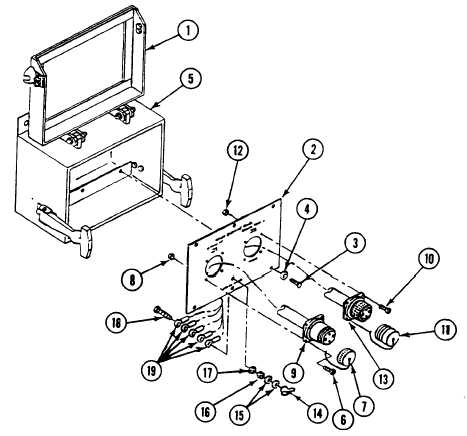
REPAIR POWER ENTRY BOX ASSEMBLY A4 (M1068A3 ONLY) — Continued
0095 00
ASSEMBLY
1.
Install five leads (19), screw (18), new lock washer (17), nut (16), two washers (15), and secure with wingnut (14) on
faceplate (2).
2.
Install cable W13 (13) in EXTERNAL POWER IN hole on faceplate (2) with cap and chain (11) and secure with four
screws (10) and new locknuts (12).
3.
Install cable W14 (9) in AC POWER OUT hole on faceplate (2) with cap and chain (7) and secure with four screws (6)
and new locknuts (8).
4.
Install faceplate (2) on power entry box (5) and secure with six screws (3) and washers (4).
5.
Close and secure lid (1) on power entry box (5).
FOLLOW-THROUGH STEPS
1.
Install power entry box (see your –20).
END OF TASK
0095 00-3/4 blank