TM 9-2350-277-20-5
REPLACE FLAME DETECTOR SWITCH
0734 00
THIS WORK PACKAGE COVERS:
Removal (page 0734 00-1).
Inspection and Repair (page 0734 00-1).
Installation (page 0734 00-2).
INITIAL SETUP:
Maintenance Level
Unit
Tools and Special Tools
General Mechanic’s Tool Kit (WP 0926 00, Item 65)
Personnel Required
Unit Mechanic
Equipment Condition
Coolant heater and pump unit removed (WP 0728 00)
REMOVAL
1.
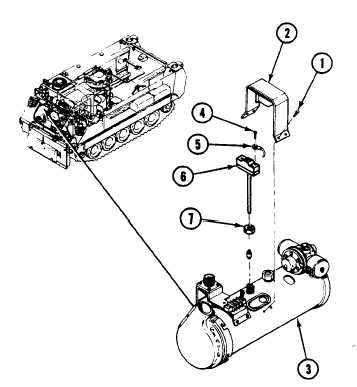
Remove four screws (1) and guard (2) from heater (3).
NOTE
Tag all leads before removal.
2.
Remove five screws (4) and leads (5) from flame detector switch (6).
3.
Loosen nut (7) on switch (6). Pull switch straight out from heater (3).
INSPECTION-ACCEPTANCE AND REJECTION CRITERIA
1.
Check leads and connectors. Replace worn leads and damaged connectors (WP 0382 00).
0734 00-1