TM 9-2350-277-20-3
ADJUST TRANSMISSION BRAKES — Continued
0394 00
NOTE
If power plant is not in carrier or if linkage is not connected to transmission, do Step 4 to adjust
left-hand brake.
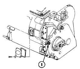
If arm is not on transmission, use splined socket to apply torque to shaft.
Combination wrench turned to right (counterclockwise rotation of adjusting link) tightens
brake. Combination wrench turned to left (clockwise rotation of adjusting link) loosens brake.
If indicator stopped before APPLY mark, brakes are too tight. If indicator stopped past mark,
brakes need to be tightened. Brake adjusting link should be turned only 1/6 turn (60 degrees) at
a time until proper brake adjustment is achieved.
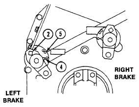
4.
Apply 40 lb-ft (54 N m) torque to shaft (1) or arm (2). Turn brake adjusting link (3) with an angle-head wrench until
indicator (4) lines up opposite APPLY mark (5).
NOTE
If power plant is in carrier, do Step 5 to adjust left-hand brake.
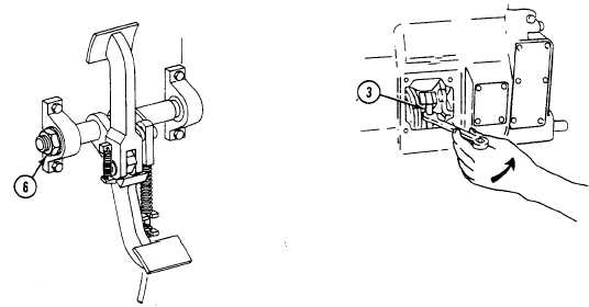
5.
Apply 104 lb-ft (141 N m) torque to brake shaft nut (6). Turn brake adjusting link (3) with an angle-head wrench until
indicator (4) lines up opposite APPLY mark (5).
0394 00-3