TM 9-2350-277-20-3
REPLACE MAIN LIGHT SWITCH
0283 00
THIS WORK PACKAGE COVERS:
Removal (page 0283 00-1).
Installation (page 0283 00-2).
INITIAL SETUP:
Maintenance Level
Unit
Tools and Special Tools
General Mechanic’s Tool Kit (WP 0926 00, Item 65)
Personnel Required
Unit Mechanic
References
See your -10
Equipment Condition
Engine stopped (see your -10)
Carrier blocked (see your -10)
Battery ground strap disconnected (WP 0337 00),
(WP 0338 00), or (WP 0339 00)
Instrument panel removed (WP 0295 00)
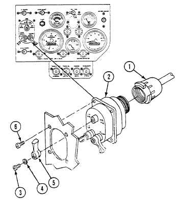
REMOVAL
1.
Disconnect cable (1) from main light switch (2).
2.
Remove screw (3), washer (4), and switch lever (5) from light switch (2).
3.
Remove four screws (6) and light switch (2) from instrument panel.
0283 00-1