TM 9-2350-277-20-2
REPLACE THERMOSTATIC FAN SPEED SWITCH
0231 00
THIS WORK PACKAGE COVERS:
Removal (page 0231 00-1).
Installation (page 0231 00-3).
INITIAL SETUP:
Maintenance Level
Unit
Tools and Special Tools
General Mechanic’s Tool Kit (WP 0926 00, Item 65)
Materials/Parts
Sealing compound (WP 0928 00, Item 56)
Packing
Packing
Packing
Packing
Personnel Required
Unit Mechanic
References
See your -10
Equipment Condition
Engine stopped (see your -10)
Carrier blocked (see your -10)
Power plant upper rear access panel
removed (see your -10)
REMOVAL
1.
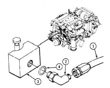
Remove oil supply hose (1) from elbow (2) on thermostatic switch (3).
2.
Remove elbow (2) and packing (4) from switch (3). Discard packing.
0231 00-1