TM 9-2350-277-20-2
REPLACE FUEL RETURN HOSES, TUBES, AND FITTINGS (M113A3, M901A3, M981A3,
M1059A3, AND M58 ONLY) — Continued
0195 00
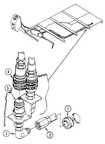
31. Install quick disconnect coupler body (4) on quick disconnect coupler nose (5).
FOLLOW-THROUGH STEPS
1.
Fill fuel tanks (WP 0177 00).
2.
Connect battery ground strap (WP 0337 00) or (WP 0339 00).
3.
Start engine (see your -10). Check for leaks.
4.
Stop engine.
5.
Install floor plates (WP 0539 00), (WP 0540 00), (WP 0541 00), (WP 0542 00) or (WP 0545 00).
6.
Install power plant lower rear access panel (see your -10).
7.
Install smoke generator fog oil tank module (M1059A3 only) (WP 0753 00).
8.
Install smoke generator system (M58 only) TM 3-1040-285-20
9.
Start engine (see your -10).
10. Raise and lock ramp (see your -10).
11. Stop engine (see your -10).
END OF TASK
0195 00-13/14 blank