5-10
Change 4
TM 9-2350-267-34
COOLING FAN DRIVE ASSEMBLY REPAIR (CONTINUED)
R
s
T
U
V
NOTE
Backlash between gear shaft and draft shaft must be
between 0.002 and 0.004 inch.
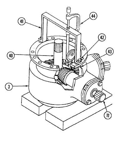
Perform steps R through W to check backlash.
Set cooling fan drive assembly (3) on support blocks on a flat surface.
Install fabricated fan drive bracket (41) in line with bevel gear case
assembly (11) on cooling fan drive assembly (3) with two screws (42)
and nuts (43).
Install dial indicator (44) on fabricated fan drive bracket (41) with
plunger positioned on bevel gear teeth.
Hold drive shaft (40) secure to prevent any movement and rotate gear
shaft (11) counterclockwise as far as possible. Do not force.
Zero dial indicator and slowly rotate gear shaft (11) clockwise as far
as possible. Do not force. Read backlash measurement.